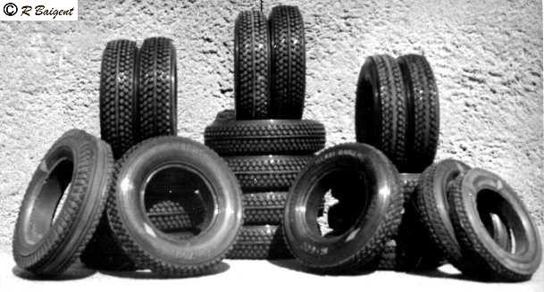
One of the really almost insurmountable problems in modeling cars was the production of wheels and tyres that do not look like toy ones. Henri delved into rubber moulding and produced his own tyres. These were developed from around 1947, when as far as I know, this process had not been considered. Some of the earliest tyres are shown in the pile below. A note that a national journalist made on the reverse side of the photo was, "Fort Dunlop? No, just a pile of Baigent's own moulded racing tyres looking for all the world like the R3 pattern." It was a part of my personal responsibilty to make considerable numbers of these for sale to other modellers during the early days of our development.
above right, solid tyres by the hundreds were the first development, but these added too much weight to the cars so the lighter pneumatics were developed.
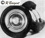
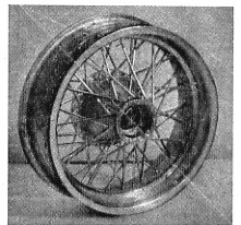
above, high-speed 'pneumatic' light weight wheel and tyres, wire beaded, and capable of withstanding the forces of rotating at 30,000rpm. Special wheel design with a split rim enabled the tyres to be fitted without straining the beads. Wheel and tyre weighed 1oz (3gr), and were 2.25in in diameter. The price charged was 15 shillings each wheel of this design in 1949.
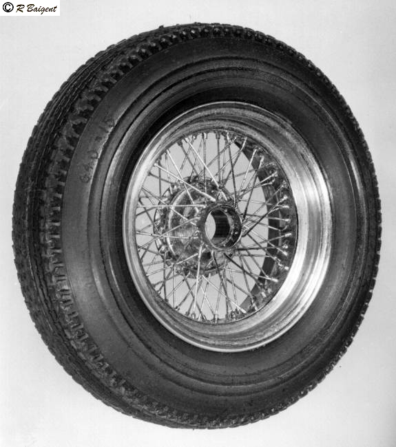
Later, spoked wheels evolved due to demand and Henri became the front-runner in this field, writing for magazines as seen below. They cost 3 pound sterling each and came complete with brake drums to match. They weighed 1oz per wheel, and were safe up to a rotational speed of 10000 rpm. The spokes were high-tensile steel wire. click on picture for larger image.
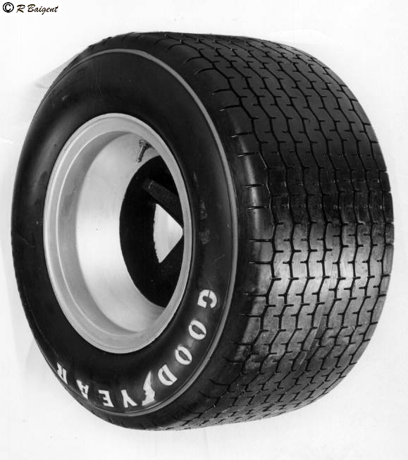
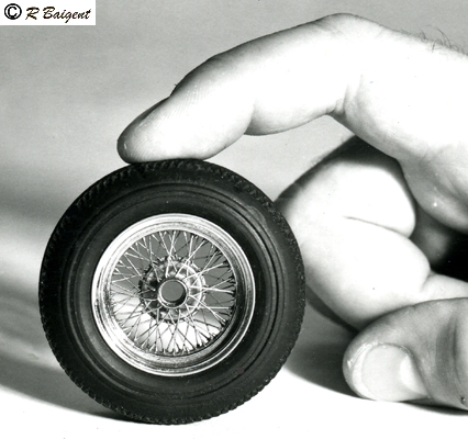
During the late 1960s a model of a Lotus 49 was built for the Ford Motor Company. above, an example of a wheel and tyre made for that model with the tyre tread absolutely true-to-scale, click for larger image.
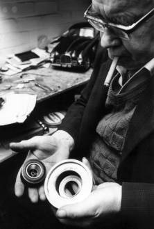
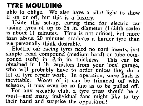
Henri posing for a press release with the Lotus Ford finished wheel and tyre and the tyre-mould that was used for the Lotus-Ford project.
The magazine, The Model Maker, now demised, at the end of 1950, published a series of three articles written by Henri. As some modellers may not have seen the techniques before I feel that I should enable them to read them now. Most wheels produced were the classic Rudge-Whitworth double-butted triple-spoked wheels with 72 high-tensile steel spokes. These were assembled in a home-made jig. I think the diagrams cover most aspects of manufacture. If you click on the pictures below you will be able to read the master's advice. I was so lucky to be introduced to a modeller who had part 2 in his possession and who kindly lent it to me to enable me to complete this page. Thank you very much, David Goddard for your kind help in lending me the magazine with part 2 in it.
Extract from Model Maker December 1950:-
The factor most often taken into consideration in the early stages of planning a model car, is its wheels. The problems involved are usually twofold. Firstly comes the question of whether the full-sized car has wire wheels/and if so, can the finished job possibly look right, if these are omitted. Nine times out of ten, the answer is "No, it'll look dreadful!"
The second problem is that of tyre sizes; time and again in reading accounts of model car building, the opening stages contain the words: "The job had to be scaled to suit the tyres I had by me" or, "was able to obtain commercially". An inconvenient state of affairs to say the least of it. Even fewer than those who boggle at the idea of wheel making are those who contemplate making their own tyres, and/indeed the idea is somewhat "bogglesome" at first sight! Such a course, however, would often solve a number of other problems in a single stroke.
Many readers have in the past admired the perfection of H. C. Baigent's little racing models, and the highest praise is always for his perfect little scale wheels and tyres. When our friend offered to describe his own methods, step by step, and added that, although he actually makes these little masterpieces for sale to the public, his methods were within the scope of any average amateur with a home workshop, we naturally accepted his offer with alacrity, and warm thanks for his candid revelations of what some people might justly claim to be "trade secrets". (ed)
Make your own TYRES and WHEELS Part I by H. C. Baigent
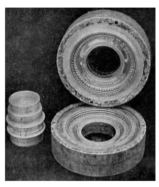
This picture shows the core and 2 mould halves with tread turned and punched with polished dural faces.
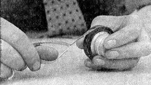
Showing how the cushion gum is wound onto the core with the non-sticky linen backing being peeled off in the process.
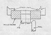
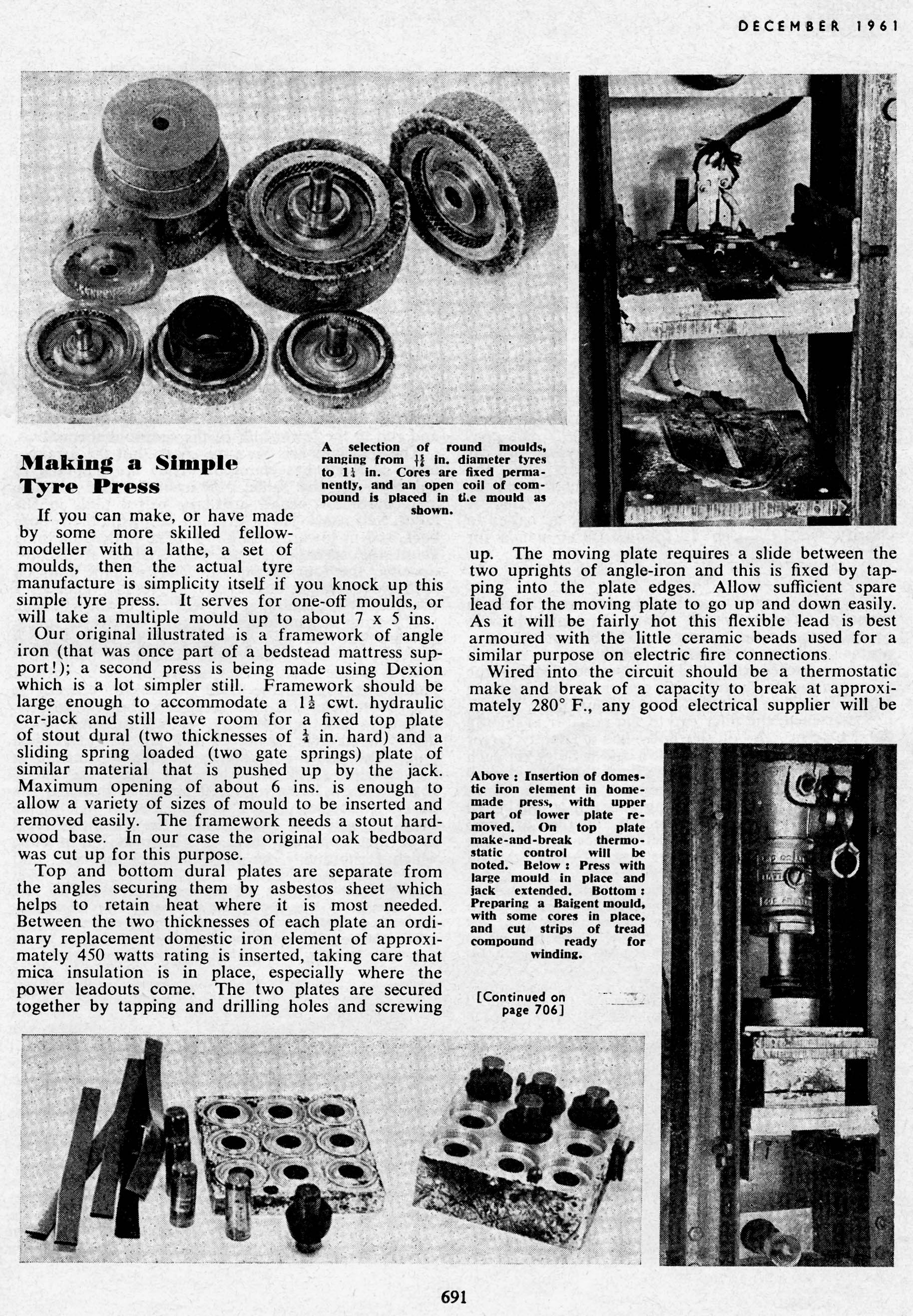
Anyone can make their own tyres provided they have a normal workshop, the main essentials in which are a small lathe and a large vice or a small press (a book press will do). There are one or two smaller essentials, but these can be obtained for a few shillings. The main things are two metal plates as massive as possible to, retain the heat; I use two pieces 6 in. wide, 10 in. long, and 1 in. thick these are of steel and can be bought at most metal dealers, as they are cut off standard rolled bar, which also has the advantage of being of equal thickness. Secondly a piece of round dural or, aluminium for the mould, the size of this depending on the size of the tyre. If I come up against any difficulty in obtaining large diameter dural I melt a scrap dural and run it in a deep tin lid and work from that.
Readers may say "it's all right for you to say you only want this and that, but what have you got?" Actually I have a 3.5 in. Myford lathe, a small 1/4 in. drill, a home-made press, and a small tortoise stove, and that's all, so you see special equipment is unnecessary. As to material, if you go along to any firm doing tyre re-treading and tell them what you want to do you will find as a rule that they are very interested. The material you require is 1/32 in. "cushion" gum about two or three pounds will make dozens of small tyres; and a small quantity of pre-stretched cord made for the repair of walls inside full-size tyres. You don't require much of this, but don't buy less than 24 in. lengths, and as the width is about 20 in. this will be enough to last out your "cushion" gum. Both these articles only cost a few shillings.
In the following articles I am describing both tyres and wire wheels, but I am dealing with tyres first, as, it's no good making beautiful scale spoked wheels if you can't get tyres to fit them.
The first thing to do is make the mould. This can be made from any metal, but dural or aluminium is definitely the best. Should you use brass it must be chromium-plated on the mould faces, or the rubber will adhere to the brass.
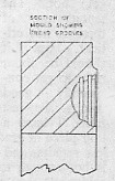
I am going to describe the mould with one or two sketches, but add no dimensions as the size depends on your requirements.
There are three parts to the mould: top, bottom and core.
The shape of the core depends on the shape of the rim, and this you must determine
first. Mine is like this and is about 3/32 in. deep at the
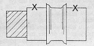
deepest points, The extra piece shown shaded is for holding in the vice as the
two surfaces marked X have to locate the mould for centralization and must therefore
be not more than .005 in. smaller than the core of the mould and not less than
.002 in., otherwise sticking will result.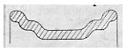
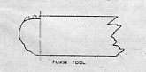
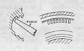
Before making the moulds I first determined the shape by scaling down a full-size tyre and making a cross-sectioned drawing to the size wanted. A form tool was now made to match half of this, thus ensuring that both sides of the mould would be the same. The tread grooves have to be put on after the forming. A gauge must be made to locate the form tool to ensure centralization. I made a plug to fit core of mould (in my case 11/4 in.), and bolting to the face of this a plate, using the end of this as a stop to bring my form tool up against before entering. After the form was cut I cut in 2 1/2 in. grooves, the half of one groove making a whole when we contact the other half of mould, but the design of tread depends on what you wish to copy; you can't very well copy the larger tyre treads exactly as this would mean an engraving machine, but you can simulate the main pattern.
After grooves were turned I put impressions on the mould, as shown very clearly on the photographs, using a punch of the desired shape, and one good sharp tap with a 3/4 lb. hammer was enough. These impressions were placed like this giving a very realistic affect.
Now the fitting of mould and core which must all come together. Note that the mould must be highly polished it a really clean job is desired, as every turning mark will show.
Now let's assume that you have everything ready. Plates, mould, rubber, some form of heat, and (this is important) two pieces of thick cloth or carpet to hold the hot plates and mould with.
First put the two plates on the fire or gas to get hot. The temperature of these is not critical, but it should be about right to get consistently good results. To test mine, I have a thin piece of grade 3 solder, such as is used on wire-less repairs, and when the top surface of the plates is hot enough to just begin to melt the end of the solder rod they are just right; if they melt it quickly they are too hot.
Now to commence building the tyre. First cut 5 or 6 strips, complete with linen, off the width of the "cushion" gum, a little wider than the finished tyre, with one slightly narrower than the others. This is the first one to wind on. Now tear off a strip of the cord rubber, tearing down the length of the cords, about 5 or 6 cords wide is enough. Let me stress here one point, don't let the uncured rubber surfaces come together while preparing them, as if they do they will stick beyond separation, so keep the linen on- till you actually wind on. First wind on to the core the narrow piece, stretching slightly as you go, as shown in the photo. Secondly, wind the cord fairly tight about five complete winds then continue winding on plain rubber till you have enough; this will be when it looks a little too big to go in the mould!
Now put the core in the mould and press together in the cold vice. If it goes right up together you have not enough in. So add some more till it is difficult to press. Have two small pieces of wood ready to go between the hot plates and the press, to insulate heat from the press, otherwise the heat would leave the plates too quickly and spoil the tyre.
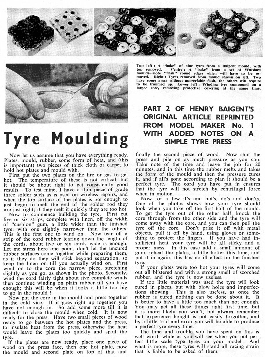
If the plates are now ready, place one piece of wood on the press face, then one hot plate, now mould and second plate on top of that, and finally the second piece of wood. Now shut the press and pile on as much pressure as you can. Take note of the time and leave the job for 20 minutes, and in this time the rubber melts and takes the form of mould, and then the pressure cures it, and if all has gone according to plan it should be a perfect tyre. The cord you have put in ensures that the tyre will not stretch by centrifugal force when in motion.
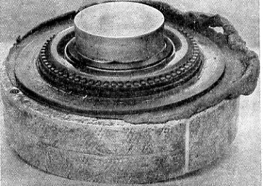
fig 9, how the job should look when the two halves are knocked apart after heating and curing the rubber. Note the clean tread pattern.
Now for a few if's and but's, do's and don'ts. One, of the photos shows how your tyre should look when you take off the first half of the mould. To get the tyre out of the other half, knock the core through from the other side and the tyre will come away with the core, and you can then pull the tyre off the core. Don't prize it off with metal objects, pull it off by hand, using gloves or something to protect the fingers. If you have had insufficient heat your tyre will be all sticky and a proper mess. In this case add a small amount of gum, reheat the plates, a little hotter this time, and put it in again; this has no ill effect on the finished tyre.
If your plates were too hot your tyres will come out all blistered and with a strong smell of scorched rubber, and the tyre is now useless.
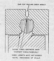
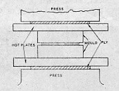
fig 10 fig 11
If too little material was used the tyre will look cured in places, but with blow holes and imperfections showing. This is also useless, as once the rubber is cured nothing can be done about it. It is better to have a little too much than not enough. You may get all these things right first time, but it's more likely you won't, but always remember that experience bought is not easily forgotten, and by a little trial and error you will be able to produce a perfect tyre every time.
The time and trouble you have spent on this is well worth while as you will see when you put perfect little scale type tyres on your model. And what is more, these tyres will stand all the racing strain that is liable to be asked of them.
Extract from Model Maker January 1951:-
Make your own TYRES and WHEELS Part II by H. C. Baigent.
Last month H. C. Baigent described the making of tyres of a high degree
of realism which would at the same time
stand up to racing speeds on small models. In this issue he goes on to
describe the building of true-to-scale wire
spoked wheels upon which to fit these tyres. As he stated at the outset,
the equipment required is not very elaborate, and although those who wish to
produce really first class wheels must of
necessity go to some trouble to
achieve satisfactory results, all the special tools needed for the job
can be produced from odds and ends by the average amateur worker in his own workshop.
Form Tools
Rim Tools.These are best turned from bar, and can be made from cast steel or mild steel and deeply case hardened; the latter will last for three or four sets of wheels if done properly.
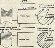
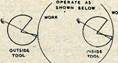
It's much easier to turn these tools to shape. You don't have to worry about undercuts or reliefs, and you can keep sharpening without losing shape. The two tools should match with about 1/32 in. clearance.
If you can reverse direction of your lathe, set the tool to work upside down with the lathe in reverse, minimising chatter.
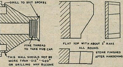
Suitable Drills.This, is a sticky problem, as on small wheels you will be working to 0.018 in. dia. to suit 26 s.w.g. wire, and drills of this size are not only difficult to get but will "run" when brought in contact with small round surfaces.
To overcome these difficulties I used No. 9 needles, allowing only about 3/16 in. projection from the chuck, and there has never been any tendency to run, when used direct on to small diameters without any guide or centre pop. Make your drills as per sketch with a smooth hand stone (not a grinder, or else you will see your drill disappear before your eyes).
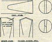
Break off the needle about half-way down the shank and stone a flat on each side, leaving a very slight flat on the end. Now stone lightly at an angle across the
top till just past halfway. This will give the cutting angle; now reverse the drill and do the same on the other side, and the result will be a diamond drill.
This will go
through a thin wall of brass very quickly,
and true to size.
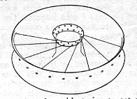
Simple Dividing Head
using standard gear wheels. The dimensions depend
on the largest wheel one intends to make, and
the sketch is only given to convey the idea of construction, actual
measurements being left to the constructor.
Very useful gearwheels for this tool can be bought from Messrs. C. C. Whitney & Co. Ltd.,
Correct spacing of spoke holes in the tiny hubs and rims is ensured by means of this simple home-made dividing head, details of which are shown on the right. The outer hub spoke holes are being drilled in the picture above.
Spoking Arrangement.
Continental.28
spokes on back row; 24 spokes on front row.
Rudge Whitworth 2 row42 back row, 28 front
Rudge Whitworth ; triple
row-Rim: 14 back, 56 front; Hub: 42 rear, 28 front.
Assembly jig. for 52 spokes wheel (24 front, 28 rear).
Reamer
for rim holes.Stone four flats on 1/32 in. drill shank and hold in
pin chuck.
A small brass
block with a hole drilled in it will make an
excellent spoke bender (hole same size as drilled in rims only). Bend spokes one end only. Drill approx. 1/16 in. deep.
Turn small grooves as shown in rim. These have two uses, to assist drilling, and as a help in the building up of strength with solder.
Tube cutter for recess in back of hub.This is a piece of round mild steel, bored out to leave a wall of approx. 1/16 in., cut saw fashion, and then case-hardened. If silver steel is used the teeth are apt to break off.
Form Tool for Hub.This tool is quite a simple form, made from 1/4 in. plate filed to shape and. then hardened, getting the working tip red hot and quenching to prevent breaking under stress.
Extract from Model Maker February 1951:-
Make your own TYRES and WHEELS Part III by H. C. Baigent.
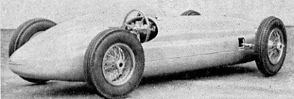
This B.R.M. model is a neat example of the satisfying touch lent by authentic wheels and tyres to racing models
Let us assume you have now got your rims and holes drilled, and your spokes cut according to your requirements, and you are ready to commence spoking. I think it would be advisable here to just run through the bits and pieces you should have in front of you
Rims, hubs, two sizes of spokes, assembly jig. reamer, bending block, pair of strong tweezers, solder, soldering iron, some sort of flame heat, such as a methylated lamp, and a small quantity of cold water in an open top container for cooling purposes. Now then, away we go.
First cut a small thin strip of solder and push it into the circular cavity at the back of the hub. Do not put top much in. I use a thin sheet solder that you can buy in what appears to be tubular form, but it is actually only folded over; this I open out and cut strips off.. In the 2 ¼ in. wheels I use a strip approx. 1/16 in. wide and just long enough to make one ring. Now place hub on jig, which should be a fairly tight fit to ensure that it does not move during the spoking. If you find it is a little loose, a simple way of making it fit is to place three small pieces of thin paper equally spaced round the jig before pushing the rim on, then tear off surplus. Of course, if rims and jig have been made correctly this should not be necessary, but mistakes are easy to make and there is no reason why a rim should be rejected for the sake of a couple of thousanths of an inch
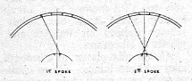
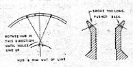
Start spoking with the rear row, bend only just so that much of the spoke that goes on the hub, then select any one hole in the rim and ream it to take the direction to the corresponding hole in the hub. Now ream the fourth hole from that one inclusive in the opposite direction, and place the two spokes in position. You may find that the spokes do not look right, such as below If this is so, release the centre screw and turn hub till they become centralized.
Now at this stage it pays to put two spokes in the front row on the opposite side and this will show you if the two rows are going to line up; you might find they don't, and although it will, only be very slight, remember that it is the front ones that want to be right, as they are the most obvious when the wheel is finished: So get your front ones right, and if the back ones are very slightly out it won't matter
You can now finish the back row and sweat in the centre by holding the jig complete over a flame, and when hot drop some Baker's fluid round the hub and it will be found that the solder you have placed in the cavity will come through and run all round the spokes. (Only fix hub spokes at this stage -all the ends in the rim are fixed last.) Now slip the whole in cold water. This normalizes the Baker's fluid and stops it corroding the jig, which as you see must be dural or the whole thing will become soldered solid
Now you are ready for the front row. The sequence is the same as for the rear, but the bend is not quite so sharp as the spoke is longer, and the holes have to be reamed sideways and upwards as the spokes lean both sideways and outwards. It is, found best to spoke the underneath ones first, that is the lowest of the staggered holes in the hub.
This saves a lot of trouble trying to get spokes in under others. When all the front spokes are in you are ready to fix ends, etc., and finish off.
Start fixing the centre ends in the hub first, for which you will need the soldering iron, First push back the ends of the spokes in the hub till they only just protrude through the metal of the hub, otherwise they will foul the hub caps.
A set of hubs drilled and ready for spoking. Note the staggered holes. Extreme right: The finished wheel after plating showing the form of the "well-based" rim.
Now solder by holding the soldering iron on the ends and slowly revolve the wheel and keep the iron there until the solder runs right through to the other side fixing spokes both sides very firmly.
Now file off any surplus spoke ends that protrude through the rim, then round the two rows together. I find it's best to preheat the whole over a flame and introduce flux when hot, then when you run round with the iron and the solder runs easily and through the rim and makes a very solid job. Now dip the whole again and remove from the jig, and you have a finished wheel which should be dead true and a pleasure to look at. It is now ready for plating. I have had quite a lot of bother getting these small wheels plated satisfactorily, and have fitted up a small nickel bath which gives very satisfying, results, and I shall be following this article with full details of construction and working of a small plating bath.
and finally, an extract from The Model Maker written by Henri about making tyres
click on pictures to read enlargements
Author's request! If anybody has this article about electro-plating to hand would you please let me know by e-mail?

![]()
![]()